| Japanese | English |
Realtime Analyzer's oscilloscope is a convenient tool for testing audio devices when it is used with the signal generator. Polarity check, time alignment adjustment, and distortion measurement can be easily and intuitively performed by comparing the waveforms of the input and output signal of the audio system. In addition to the audio devices, any electronic circuit can be measured by using the oscilloscope probe or multi-meter as input. See how to use the electronic probe with PC.
The simplest way to measure the performance of the audio amplifier is to input the sinusoidal wave to the amplifier, measure the output of the amplifier, and compare it with the input waveform to know how much the signal is changed.
To observe the input waveform (signal generator's output) and the output waveform of the amplifier at the same time, set up your measurement system as follows.
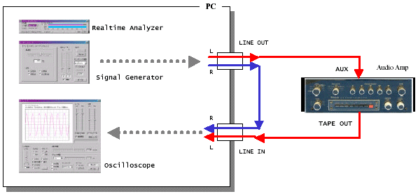
Now, you can observe two waveforms on the oscilloscope screen at the same time. The right channel of the oscilloscope shows the input waveform (reference signal), and the left channel shows the output waveform.
Polarity check
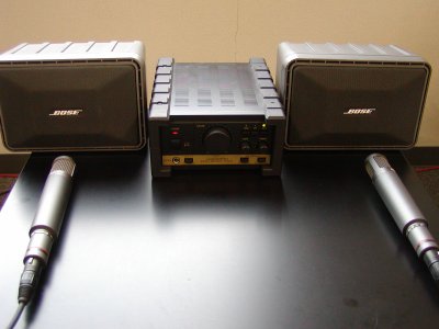
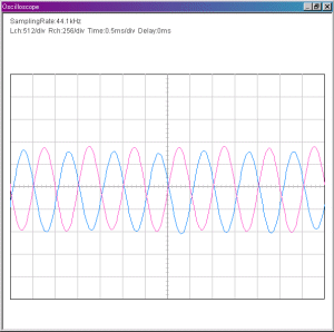
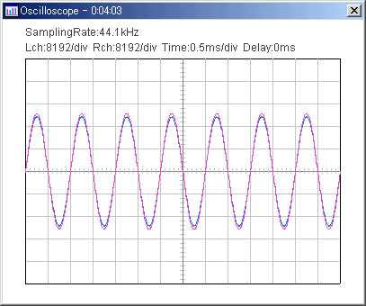
There is probably a difference in the amplitudes for these two waveforms. This difference represents the gain or loss of the devices under test, so it may be safely disregarded. It is important that the two sine waves must have the same polarity. It means that positive and negative peaks must be at the same horizontal position on a monitor. If the waveforms are reversed, then there has been a reverse in polarity. This means that there may be an error in line connections or a problem unique to one of the devices. In any case, the problem must be corrected. An example is the phase check of the stereo speakers. If the speakers are connected out of phase, the outputs of the two speakers will be subtracted each other. Then, it will produce very little bass and will have a poor center image. See Speaker phase check for detail.
Time alignment adjustment
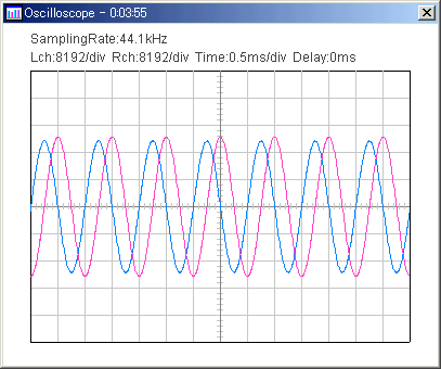
In the multi-way speaker systems, position of each unit (e.g., tweeter and woofer) should be adjusted so that the sounds from different units will be added in-phase. Otherwise, outputs of the two units will be subtracted each other and produces unwanted sound as in the case of the stereo speaker. Oscilloscope can be used for this purpose too. Measurement procedure is almost same as the above mentioned speaker phase check. The left figure is before the adjustment. A blue curve is woofer output and a pink curve is tweeter output. Woofer's output is arriving faster than that of tweeter. After the adjustment, two outputs arrive at the same time.
Check of distortion and oscillation
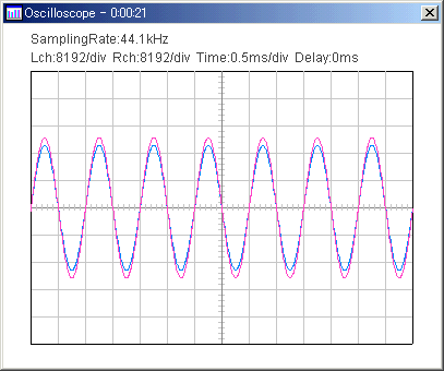
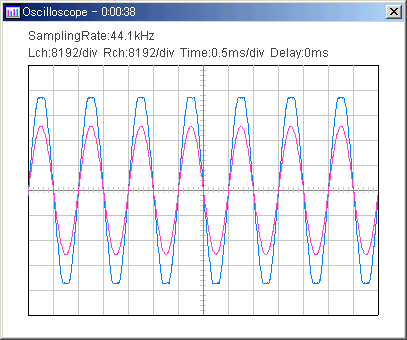
Certain distortion appears as changes in the form of sine waves. Comparatively low frequency oscillations appear as a change of the waveforms. High frequency oscillation does not change its original form, while the test sine waves appear to be emphasized. For testing the transient response, square wave might be better than sine wave. Distortion can also be measured quantitatively by using the THD analyzer. When investigating the output of the crossover network, it is necessary to confirm the frequency of the test signal is significantly higher or lower than the crossover frequency.
Those tests should be performed for all devices. Depending on the situation, it may be necessary to use a camera to take a picture of the oscilloscope waveform. A report is also required, so it is clear that a considerable amount of work is involved. Realtime Analyzer will serve to reduce both time and effort required for the audio measurements.