| Japanese | English |
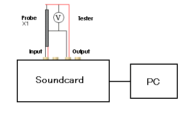
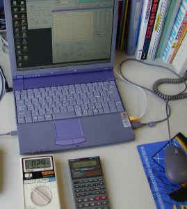
Calibration is done by feeding a test signal (1 kHz sine tone) to the soundcard and by measuring its AC voltage. Test signal is created by the signal generator, outputted from the soundcard's output, and fed to the soundcard input via the probe. Because my PC (VAIO 505) does not have line-in/out terminals, I used a USB audio interface (Edirol UA-5).
The connection setup is below. The left channel output is connected to the left channel input via the probe, and the voltage is measured by the tester's voltmeter.
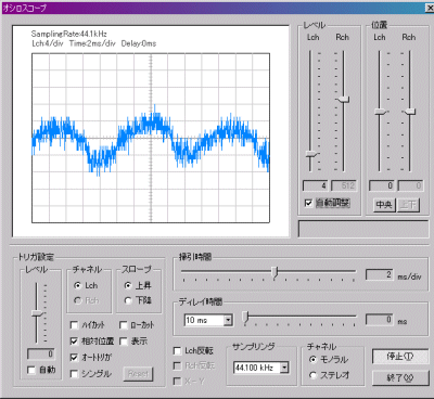
A 1 kHz sine tone is generated by the signal generator. This is the oscilloscope screen. Unfortunately, the waveform is very noisy, probably because the gain is small.
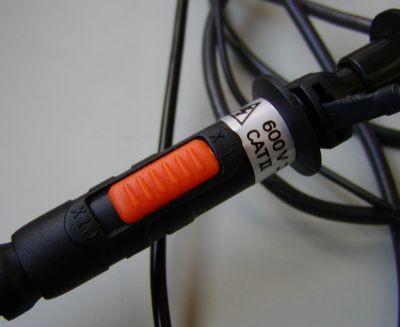
Then, the switch of a probe is changed from x10 to x1.
Now clear waveform is displayed.
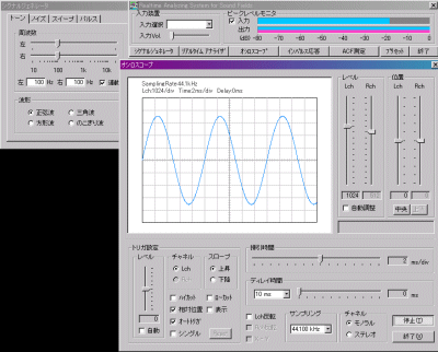
The INPUT volume of UA-5 was adjusted so that the peak to peak amplitude of the waveform becomes 2 scales (div) at the level range of 1024/div.
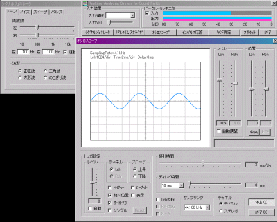
At this point, the RMS voltage measured by the tester is 0.24V. The peak value of the waveform (1div) is root2 times this value, thus 0.34V. After this calibration, the voltage of any incoming signal can be measured as 1div at 1024/div =0.34V.
Keep in mind that the calibration is needed again if you change the INPUT volume of UA-5.
Note: This is "an experiment." We cannot take a guarantee of operation and the responsibility about an experiment result. When you connect a probe to your computer, please try with your own responsibility.