| Japanese | English |
| PC | DELL INSPIRON 7500 |
| OS: | Windows 2000 Professional |
| Software | DSSF3 |
THD analyzer measures the Total Harmonic Distortion of the system. THD is a measure to evaluate the linearity of the system, and it is defined as the ratio of the geometric mean of the harmonic components (v2, v3, v4, v5, ... v30) and the fundamental component (v1) when the sinusoidal wave is inputted to the system. Usually it is expressed in dB or %.
This time, the measurement example of PC's audio performance by the RA's THD analyzer is reported.
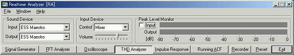
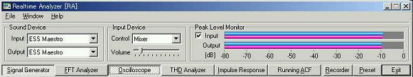
This is the main window of RA. Input device is set to Mixer (Wave) to measure the PC's soundboard. The sinusoidal wave is generated by signal generator, converted to the analog signal by D/A converter, and amplified by the analog amplifier. The amplified signal is inputted to the mixer and A/D converted. THD analyzer measures the output of the mixer.
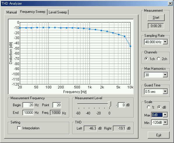
This is a window of the frequency sweep measurement in the THD analyzer. In this measurement, the frequency of sinusoidal is changed automatically and THD is measured for each frequency. Setting items are the Measurement Frequency (Begin, End, and number of measuring point) and the Measurement Level (0 dB is the maximum output level). On the right side of the window, other settings are shown. Sampling Rate depends on the soundboard's performance. Available rates are displayed. Channels is to select the measurement channels. When 1ch is selected, left channel is measured. Max Harmonics is to set the maximum harmonics to be measured. It can be set between 2 and 30. This option is made for the PC with low CPU capability. Usually, it should be measured up to 30th harmonic. Guard Time is set to avoid measuring the transient sound. If it is set short, an extremely bad measurement result will be brought especially in a poor PC. Scale is swapped between % and dB and Max and Min are also specified.
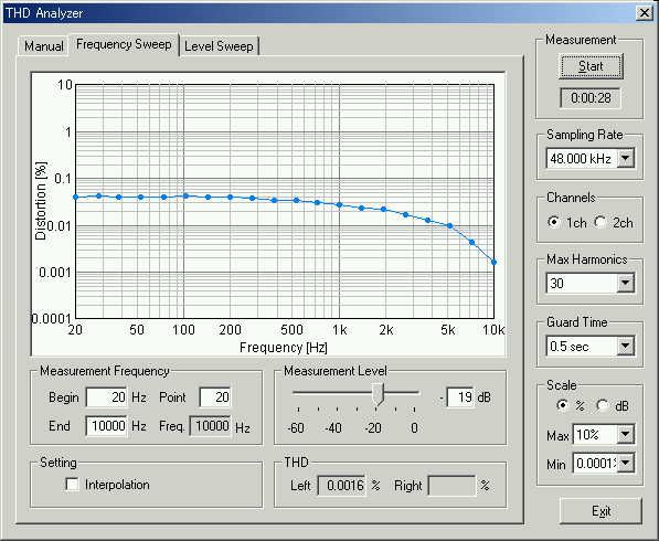
As a result, it was found that the THD is below 0.035 % between 20 and 10 kHz when the sampling rate of 48 kHz and the output level of -20 dB are used. This result shows the performance of INSPON7500's soundboard. It seems that this PC has enough performance for sound measurement.
Scale was changed to dB.
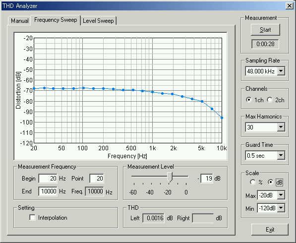
The measurement was repeated once more. Result is the same.

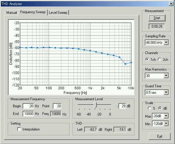
Measurement level was decreased 10 dB. Then, the distortion increased about 10 dB. This is the reason why the measurement level should not be too small.
Next, the measurement level was increased to the maximum. The result is horrible. For the sound measurement, proper adjustment of sound level is important.
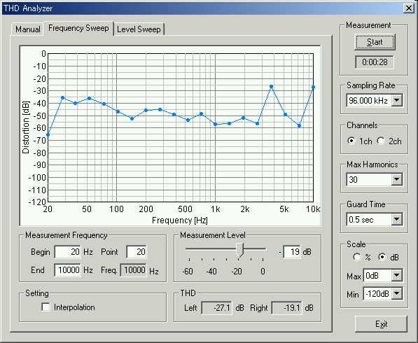
Now, the sampling rate was increased to 96 kHz. Inspiron7500's D/A converter seems to deals with the 96k Hz sampling, but the analog amplifier may have the problem. Distortion is larger than the case of 48 kHz sampling.
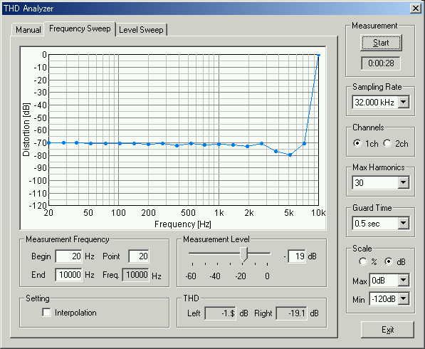
Next, the sampling rate was decreased to 32 kHz. Distortion increased in the high frequency range. It seems that the suitable sampling rate in this PC is 44 kHz or 48 kHz.
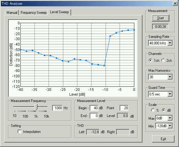
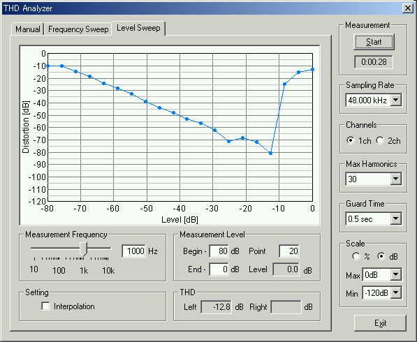
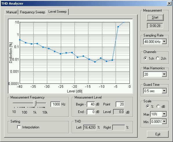
Next, the level sweep measurement was tried. The measurement level was swept between -40 and 0 dB for the 1000 Hz sinusoidal tone. From the result below, the measurement range between -10 and -30 seems good. The distortion increases rapidly from the measurement level of -10 dB. This performance is a fatal defect for the sound measurement system.
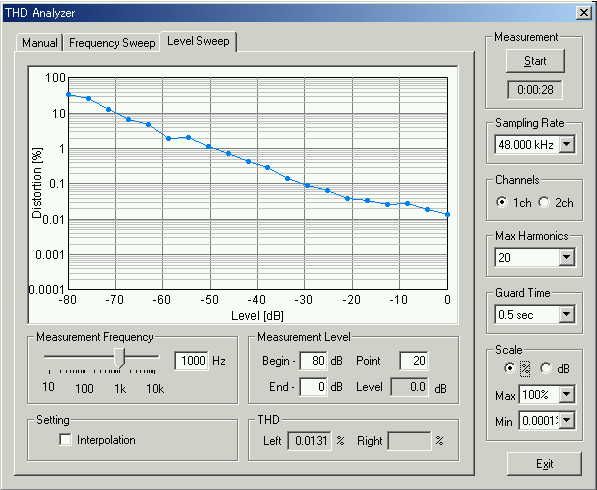
Now the measurement level range was changed between -80 and 0 dB. Again, the measurement range between -10 and -30 seems good.
This is the main window of RA. Peak level monitor shows the sound level between -80 and 0 dB.
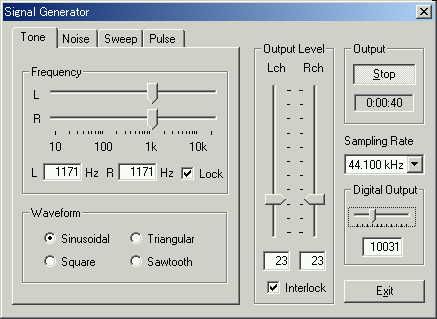
Probably, by this performance, acquisition of the impulse response seems difficult. To reduce the distortion, Digital output of SG should have been decreased to 10031.
For comparison, the measurement result of VAIO PCG-R505R/DK is shown below. About the distortion between -10 and 0dB, this is in a desirable state.

The same graph is displayed in % scale.
Measurement results of DELL and VAIO are peculiar to each PC. Another DELL Inspiron7500 was measured similarly. It seems better than the previous one. But it also has a large distortion between -5 and 0 dB.
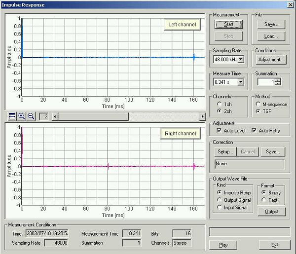
After the distortion measurement, I was afraid that the impulse response measurement could not be done well by Inspiron7500. But it was no problem. If the auto level adjustment was used, only below -12 dB was used for TSP signal output.
THD Analyzer clarifies the performance, failure, and fault of the measurement system in an instant. If the THD analyzer is used for a maintenance of measurement apparatus or a system, and a check before measurement, the accident will decrease sharply. This feature must be a valuable tool for the recording engineers and the PA engineers.
July 2003 by Masatsugu Sakurai