Total harmonic distortion (THD) is one of the most common and important specification in the audio measurement, which is used to describe the ability of the device to accurately reproduce an input signal at its output. Audio signals suffer some distortion when they pass through electronic circuits. Especially, unwanted harmonic components are added to the input signal due to the nonlinear distortion. A large nonlinear distortion is audible as a change in timbre of sound. So, it is very harmful to the audio system.
The amount of the nonlinear distortion is measured using a sine wave as a test signal. THD is defined as the ratio of the geometric mean of the harmonic components (v2, v3, v4, v5, ... ) and the fundamental component (v1). It is expressed in dB or %, and lower numbers are considered to be better.
DSSF3's THD analyzer is designed for measuring the distortion of input/output systems, like an amplifier and a soundcard. Internal signal generator is used to feed a test signal to the device under test, and its output is measured. Basic measurement configuration is as follows. For measuring an amplifier, connect the soundcard's output (Line-Out) to the amplifier's input and connect the amplifier's output to the soundcard's input (Line-In, L ch: ----). Any device can be measured by connecting it between the input and the output of the soundcard.
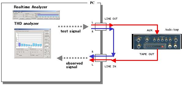
If the soundcard's input and output are connected directly (R ch: ----), distortion of the soundcard itself can be measured. This is called a loopback test, and is very important to perform an accurate measurement. If the measurement is performed with a wrong volume settings, the distortion of the soundcard itself becomes large and the correct results cannot be obtained. Before starting the measurement of external equipments, it is important to perform a loopback test to know the appropriate volume controls.
To see the effect of these three volumes, a distortion of a PC's soundcard was tested. Input device was set to WAVE/DirectSound. In this configuration, the sine wave is generated by the internal signal generator of THD analyzer, converted to the analog signal by the D/A converter, and amplified by the volume control mixer. This signal is directly fed to the mixer, amplified and A/D converted. THD analyzer measures the A/D converter's output. See the block diagram in this page.
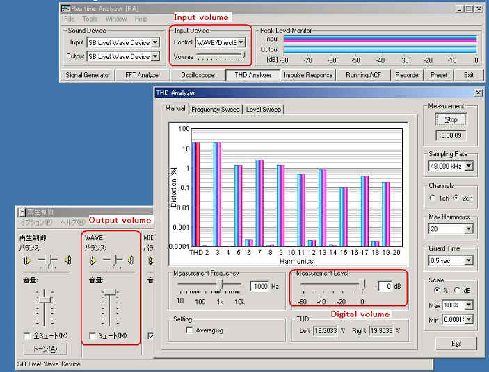
There are three volumes that control the input and output of the soundcard. The first is the input volume, that is accessed from the main window of the Realtime Analyzer. This volume is interlocked with the Window's recording control panel, and adjusts the input signal level before A/D converted. The second is the output volume, that is controlled by the signal generator's "Output Level". This volume is interlocked with the Window's volume control panel, and adjusts the level of the D/A converted signal. The third is the digital volume. This is an original function of the Realtime Analyzer, that controls the amplitude of the digital signal (wave data) outputted from the signal generator. This volume can be adjusted by the "Measurement Level" setting on the THD analyzer.
At first, three volumes were set to the maximum. We can see that many odd harmonics (x3, x5, x7,...x19) are dominant in the graph. This is a typical case where the input signal is clipped somewhere in the soundcard. As a result, THD is very high (19.3 %). Note that in this case, the input level monitor is above 0 dB.
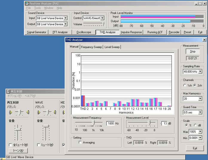
To minimize the distortion of the soundcard, these three volumes should be adjusted appropriately. A rule of thumb is to adjust volumes so that the input peak level monitor stays below 0 dB. In the next figure, the input volume and the output volume were not changed, and the digital volume (Measurement Level) was decreased from 0 dB. We found a point at which the input peak level monitor become below 0 dB. At this point, THD also decreased dramatically. In this soundcard, the measurement level of about -10 dB showed the lowest THD.
When the input volume or the output volume are also changed, you will know the appropriate measurement level by performing the Level sweep measurement. In this measurement mode, the digital volume is changed automatically. You can find the usable range very quickly.
Other measurement reports of the THD analyzer can be found in the following pages.
There is also need to measure only the output of the audio system, for example, CD player, MP3 player, and other digital audio players. In this case, we can't connect the player between Line-Out and Line-In. All we can do is to connect the player to Line-In, and play a test tone loaded on the player. Software's internal signal generator is not used in this case. It is still outputting a test signal during a measurement, but anything is connected to the Line-Out of the soundcard. In this configuration, THD analyzer is monitoring the input signal from the player and can measure the THD; the incoming signal is treated as same as the internal signal generator's output.
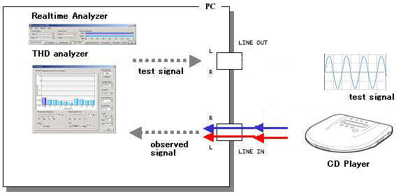
One critical thing in this measurement is to match the "Measurement Frequency" setting on the THD analyzer to the frequency of the test tone to be measured. If the frequency is mismatched, you will get a wrong result, because the fundamental and the harmonic components (v1, v2, v3, v4, v5,...) are decided using this value.
Also note that the measurement is possible only in the Manual measurement mode. Frequency Sweep or Level Sweep mode does not give a meaningful result. These measurements are valid only when the internal signal generator is used.
Finally, keep in mind that the result is a sum of distortions in the whole measurement chain, including the
player and the soundcard's input circuit. To minimize the soundcard's effect, you should adjust the input volume
of the Realtime Analyzer so that the THD becomes minimum. During a measurement,
input peak level monitor should never reach 0 dB.